Everything posted by dicky96
-
Appreciate that guys - however what I am really after is splicing in to one of the wires going to the multi plug connections just below the fuse box... otherwise yeah I will have to get to the ignition barrel or get underneath the fuse box to make a connection. It's not easy to get anywhere to connect my test meter to find the ignition live near the fuse box otherwise I'd find it. Rich
-
As the title says - can anyone tell me which wire or connection (near the fusebox) will be live when ignition is on, so I can tap my DRL power feed into it. Something easy to get to would be ideal. Cheers Rich
-
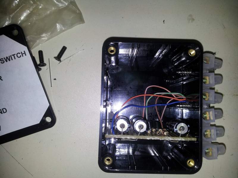
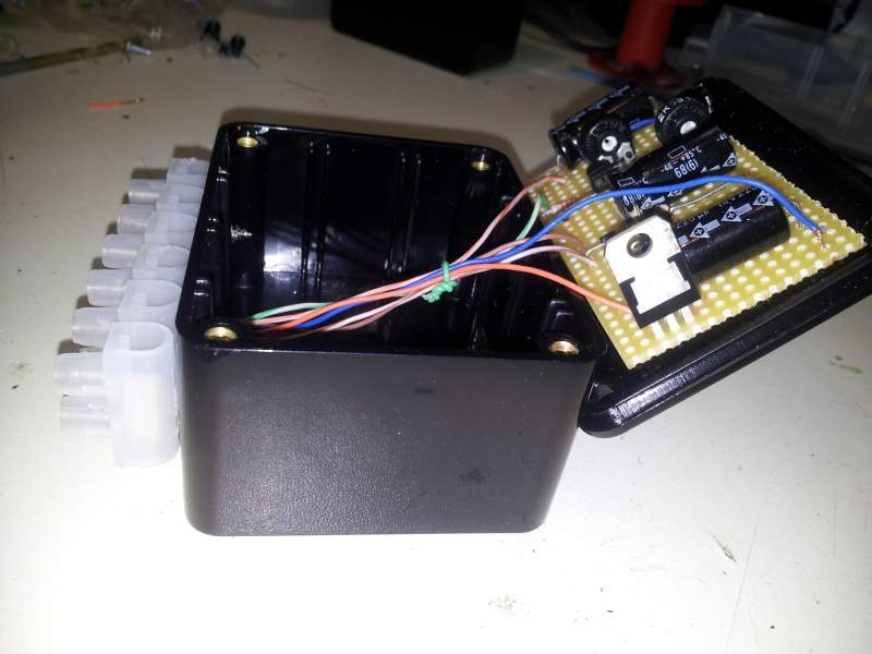
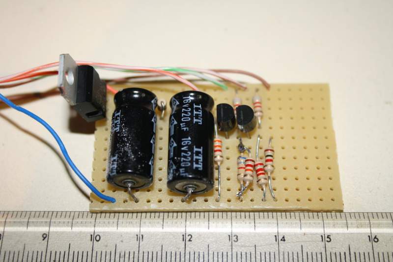
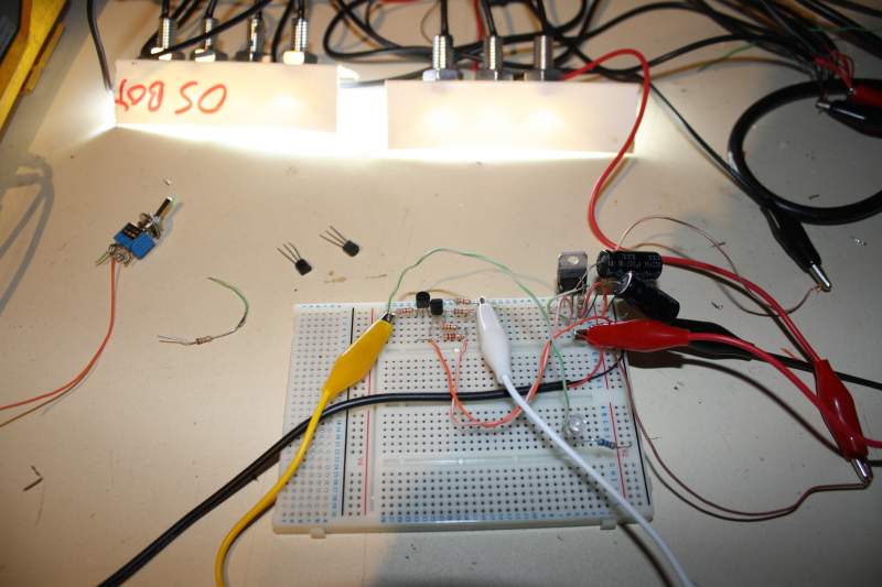
I've completed the DRL controllers and built them into a couple of small plastic enclosures I got from maplins One controller has a fixed DRL dim level and indicator delay, the other one has a couple of variable resistors (or 'pots' as they are often called) which I can adjust to match the dim level to that of the fixed DRL, and also set the time it takes so both DRLs strike at the same time when the indicators (or more imporatantly the hazard flashers) are turned off I don't need to be able to adjust both, the settings are just so I can get both sets of DRLs to match each other As I need to adjust one of the controllers in situ, I fitted the circuit board to the lid of the box so I can easily get to the variable resistors. I should have these fitted on the car tomorrow so some more pics coming and as long as they all work as intended I'll upload the circuit diagram too. Rich
-
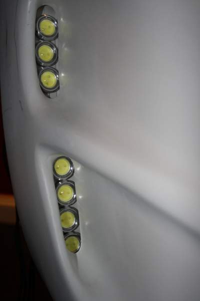
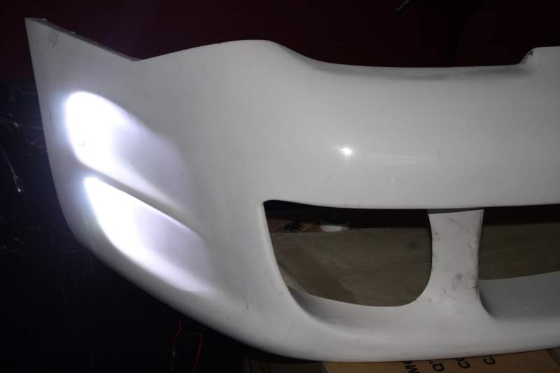
This video shows the DRLs working fitted to the bumper. They are just temporarily fitted with tape right now - but my mate who is goona do the prep work and respray on the car had a look and says no problem shortening the scoops slightly to bring the lights a little more forward so they fit correctly (as the scoop is wider toards the front) and flush to the back of the scoop. Because my camera is auto-compensating for the light level changes you can't really see the dim mode working properly, unfortunately DRLs in situ: [video=youtube_share;3Cn-L2ghA5s]
-
I've now upgraded my circuit design slightly When your indicators are flashing the DRL on that side turns off and you get teh flashing amber indicators When you turn your indicators off there is about a second delay then then DRLs fade up to full brightness (or half brightness if your side lights are on) taking about another half second or so to ramp up This needed three extra components that's all OK here are two videos - the first one shows what happened the first time I wired up all the LEDs and turned them on! First Light: [video=youtube_share;QrooA1PfpgU]
-
Cheers guys for the positive comments :biggrin: The DRLs are working quite well, next I gotta get them sitting in the scoops properly and at the correct angle. As the scoops are wider at the front than the back (where I temporarily mounted the LEDs) and the scoops are about an inch or so deep, it should be possible to cut and/or file the rear end of the scoop so the LEds fit better across the width of the sccop - by moving them forwards a bit I have a bit more width to play with, and I can also angle them in the correct direction shining directly forwards Oher than that I need to add the high brightness yellow indicator LEDs - they are pretty small and will fit in the gaps between the running lights ans especially above/below the three LEDs in the top scoop I reckon I can get 6 to 10 yelow LEDs in each section I'll also post up the circuit diagram and wiring istructions for the controllers (they are pretty simple - will do my best to explain how they work in leymans terms) Then I guess this project is completed Rich
-
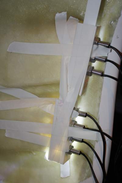
Time to try the lights and see what they do :biggrin: I've temporarily held them in place with tape You will see that the bottom one does not quite fit (bottom LED slightly obscured by the scoop edge) Also the top and botom units dont sit at quite the same angle. But they ain't too far off and don't half light up!! Gonna have a word with the guy who is gonna be doing the prep work and respray after I get the body kit fitted - see if he can do a little work on the scoop with a file or whatever to get them to sit a little better Anyway It's looking good
-
Got the first controller built Just need a small enclosure to fit it - the ruler is in cm (so it's prett small, I left about 15mm of extra board to mount it in the enclosure. It appears that the voltage regulator will not need a heatsink but I will mount a small one anyway When I built the controller I noted that the dim mode was not dimming as much as the prototype, and the off mode (for indicators on) was not quite going off on all LEDs - hence the extra resistor you can see soldered across the top of another one - this reduced he dim voltage setting by about a volt. I guess the issue was caused by component tolerances (th resistors are olnly accurate to +- 5% so that' a possible 10% difference between my prototype and the one i built When I build the second controller I will add small variable resisors so I can tweak it to give the same dim setting as this one.
-
My Home brew DRLs running on the bench with prototype controller :biggrin: Basically I have 7 x 3w LEDs each side Well they said they are 3W when they were ordered but as they draw about 80mA each I reckon them to be 1 Watt each Anyways it's no worries when you switch them all on together they light up like a supernova!! lol The controller basically handles the following functions: Ignition on = Running Lights full brightness Sidelights on = Running Lights dimmed Indicator on = Running light on selected side switches White to flashing orange Now I prototyped the circuit (it's working) I need to build two controllers, one for nearside and offside Cost of the controllers about £5 each Cost of running light LEDs (waterproof, shatterproof) £14 each side The LEDS are mounted on pieces of L section plastic (the stuff you usually us as trim for wall corners etc) My car will have the Viper V1 Front Bumper and the DRLs built into the side scoops. The L sections give me a good 'bracket' to fix them to the scoops. As there are no fitments for side lights or indicators on this type of bumper this is why I need the built in indicator function. I am using halo sidelights built into the headlight units However when I get the original nissan bumper off I will have a look at how the DRLs could be fitted to one of those To Do: Build the controllers Add multiple orange indicator LEDs to each running light set Get it all installed on the bumper
-
Can I suggest you do as I did? If the Zed is to get parked on the road outside your house from time to time, put a Camera up on the chinmney pointing at the road where the car is parked, and while you are at it get one with night vision. Only problem is - when you find that it was the next door neighrbours 17 yr old who was scratching the car, and you even go round argue the toss which they thoroughly deny - then confront them with the evidence on dvd to finalise the matter - they will still want to fight you over it!!!! So from presonal experiene take a baseball bat with you as well..... purely for self defence of course Having said that no one round here touches my car or any other of my property anymore :devil2:
-
Hmm I just upload pics direct to the forum.....
-
Did a short vid of my prototype daytime running lights on the bench - how do I upload it? its MP4
-
Some great contributions there After overnight consideration, I think I would install something like this in the passenger seat, and her mocha-coloured half sisters on the rear one for good measure (and a little variety) lol PS failing that I love that hardtop convertable!! wow And it would probably go down better with the missus.....

-
Now Now - I meant what upgrades/modifications would you do. Swapping the entire car is not fair game for the spirit of this thread lol You need to be a little more creative with something that is practical to do..... or at least technically possible
-
Not sure if this has been done here before (I've only been around a little while) but I thought it could be a bit of fun. So let's see.... Let's say you came into a 'considerable sum' of money (inheritance lottery whatever) and you had a nice pot of money left over spare to spend on your Zed after the missus had satiated herself with shoes and chocolate.... then what would you do if the cost was not of importance... and what might it cost :biggrin: Let your imagination and desires run amock Rich
-
Oh yeah forgot to mention my DRLs also include an indicator mode - flash from white to yellow.... well who needs seperate indicators? Seriously guys - give me about a week to 10 days (may need two clear weekends) to get everything in place then all will be relvealed :yes: It may even ber worth the wait lol PS totally different subject - probalbly should start a new thread... but can anyone tell me what sort of temparatures (max) are experienced on the underside of the bonnet say in warm weather (should we be so lucky) and when stuck in traffic. Also anyone know any decent adhesives that can take the temperature - carrying 'a very small load of weight' whatever it may be? :wink:
-
I've now upgraded my design so the DRLs will de dimmed at night rather than off Also my original simple design would not work off the test bench because when I finished upgrading I have LED rear side lights already and yes I will have halo front side lights (spotted my username on ebay is same as on here andy? :yes:) so I no longer have filament sidelights that the orignal design needed to work Version two will work in any case Pics soon Rich
-
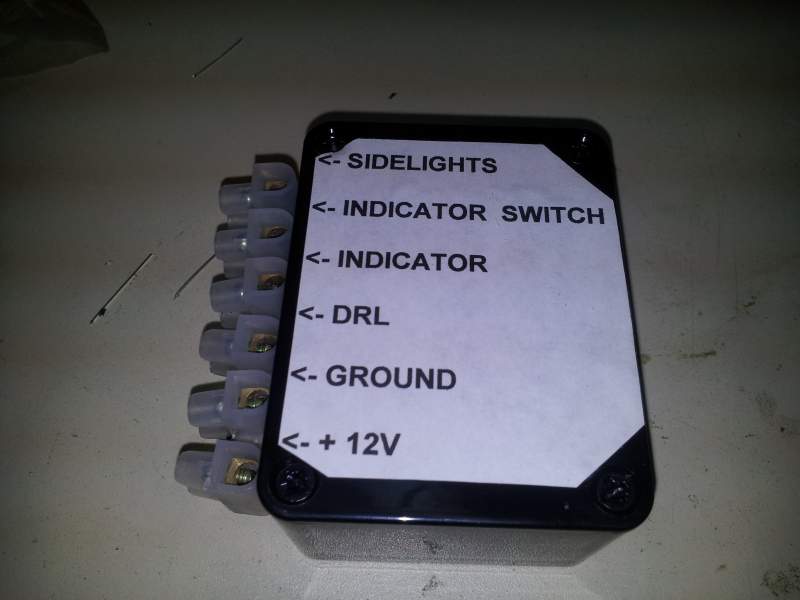
I've got this sorted so I now have Hi brightness DRLs fitted on my Z - they come on if the ignitions is turned on and go off if the sidelights are on - as per MOt regulations And for that matter they are off if the sidelights are on and the igntion is off Also silly things don't happen - like ignition lights lit on dash when sidelights on and ignition off components required - 1 Diode, 1 relay and some DLRs If it's been posted here before please save me the effort otherwise I'll put it in the FAQ section cheers Rich
-
white white white white white... oh and shiny too Mine is grey at the moment but not for long. Does anyone really like grey? Yellow is OK as long as it has a 'go faster' stripe and vinyl roof - I once had a 1973 Capri 1600S like that which proves the point for sure :tongue: Come to think of it if I still had it then it would now be worth more than my zed! How did that happen???? :blush:
-
I heard white is the new black :tt2:
-
OK I popped a tutoria in the FAQ storage section - All you need to know about LEDs Hopefully this may be of help to anyone messing around with LED lighting on their car If you like it feel free to add it to the tutorials section permanently If not I only wasted about an hour of my time lol Rich
-
Resistor colour code Bill Bloggs Raped Our Young Gladys Behind Violets Garden Wall Or Black 0 Brown 1 Red 2 Orange 3 Yellow 4 Green 5 Blue 6 Violet 7 Grey 8 White 9 So Yellow = 4 Violet = 7 Red is the third band so that is the multiplier = (2) x 0 or in other words 00 so resistance is = 4700 ohm not 472 ohm or if you like 4700 ohm = 4.7k ohm which is why your LEDS are so dim!! 470 ohm = yellow violet brown However Ohms law states I = V/R so for decent current (I) through the LED to get full brightness (say 20mA) at voltage (V) then 0.020A = 12/R or in other words R = V/I therefore R (resistance) = 600 ohms Nearest evivalnt 680 ohm Which is BLUE GREY BROWN but yeah 470 ohm (YELLOW VIOLET BROWN) (a couple extra mA) would work well enough so go for it Wattage = 12V - approx 1 Volt (voltage dropped across the LED so 11V x .02A = 0.22W so 0.25 W or greater is fine Hope that explains it Rich
-
No idea of how accurate this but it's interesting: http://www.howmanyleft.co.uk/?utf8=%E2%9C%93&q=nissan+300zx http://www.howmanyleft.co.uk/combined/nissan_300zx My jap 300zx TT manual, according to my V5, is a nissan 3litre coupe - as was my previous one so presumably does not count in these statistics Rich
-
Jeff - what CMS (forum/site content) does the site you refer to run on Reason I ask is I also own three vbulletin based sites (same CMS as this one uses) and one is a very modified vbulletin community I reprogrammed thatone so much so you would not even recognise it as a vbulletin anymore - so I may know a thing or three about the sort of stuff you are asking
-
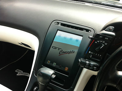
Spotted this on a Zed recently sold on ebay Fitted an ipad I believe - said it could easily be removed at night