
Everything posted by dicky96
-
OK I'm gonna try Jeffs suggestion tomorrow.... or maybe Monday as tomorrow looks like a much dryer day and I may even get chance to enjoy driving the damn thing after I did all the work - like cruise around tescos car park a couple of times posing lol :grin: However I don't hold out for total success as I read your post vods with dismay - it sounds like we have much the same problem Other than that it's staying garaged until sorted - got a fan heater running in there now in the foot well trying to dry the thing out Problem is I have to garage the car 5 mins or so walk away as there is no space to have or even build one at the house, but then it is a proper working garage (with hydraulic ramps and stuff lol) he just lets me have a key so I can access as needs be - which has gotta be a bonus PS groover - what would you know about proper wet rain.... being a southener :tt2: Rich
-
hi there rolandas do me a favour could you download the pic - add some arrows to point where to put the silicone - then upload again? Much appreciated if you could :yes: rich
-
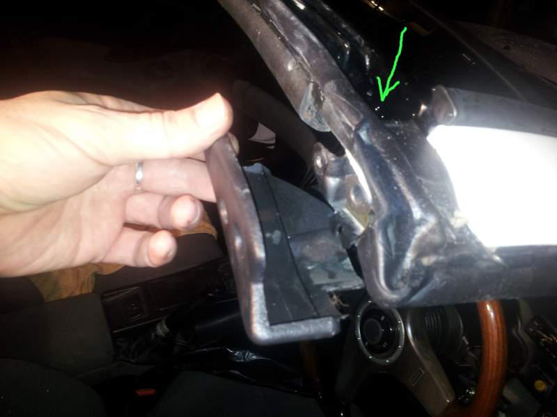
Hi znut Its like a slightly closed hole but I (gently) fed a cotter pin about 2 inches or so in.... so it definitely has a channel inside there, at least on mine @vods - no I think the larger hole is near the green arrow on my third attemp below - I wish I'd taken more notice where it is this is like pin the tail on the bloody donkey lol , but I really don't think that hole is causing the problem How do I stop the water getting into where the white arrow points?
-
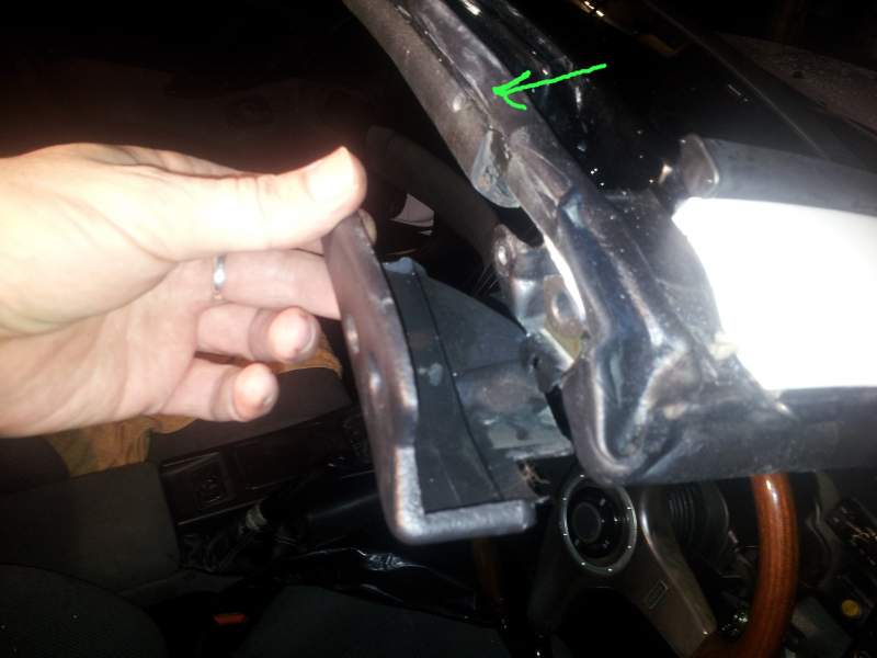
Sorry I think the green arrow should have pointed somewhere here. Anyway that hole is clear
-
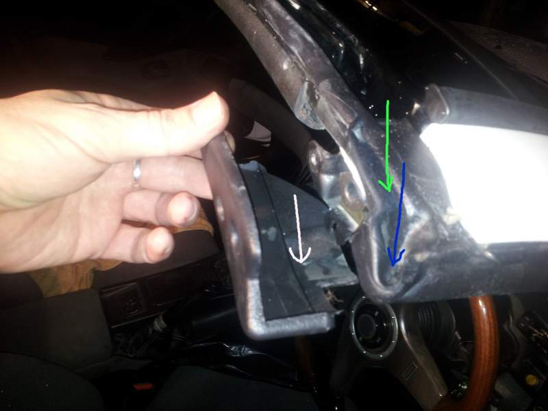
OK guys First of all I now have car garaged to save any further water damage to the interior I did a bit of experimenting, smearing vaseline over the joint between the end of rubber seal on the roof and and the end of the targa rubber made no difference. I've now rubbed the vaseline back off again I've now got the guage pods off the windscreen pillar and taken the end plastic cap off the rubber and can see what it happening. The plastic cap is filling with water which is running down the guage pod plastic and into the top guage filling it with water and dripping out from the bottom of the guage. If the top guage gets full it starts to drip from the middle guage as well There is a round drain hole near the end of the roof rubber about 5mm accross (somewhere in the vincinity of the green arrow on the pic) and that is clear. There is no build up of water in the channel of the rubber across the front of the roof anyway so it's all going somewhere. There is another very small drain hole in the rubber itself (see the blue arrown on pic) and that must be clear as I can see some water comes out at the bottom of the ruber near the door hinges The problem is what a lot of water is getting into the plastic end cap (white arrow on pic) and this is what floods into the guage pods So I can see what the problem is now, but how do I fix it? Rich
-
What am I looking for when I check the rubber down that side of the screen. It is definitely only leaking through that side I now have a mug balanced on the corner of the seat on top of towels, to catch the continuous dripping which is just coming off the bottom edge of the top guage (one place) Has anyone tried putting a big splodge of vaseline on that corner of the targa rubber as a temporary fix? I doubt vaseline would do any harm to the rubber?
-
Funnily enough i already decided last night to put bin bags on my seats! Seems like great minds think alike here lol But seriously I can check the rubbers that run down the pillars but I don't in all honestly know what I am looking for apart to see if they are there are not. Which no doubt they are Hmm was Zworld xmas meet last weeknd or this weekend.?.... The car could do with a run after 3-4 months standing and plying with alcohol may get some results one never knows lol dicky
-
Well actually I was gonna start the split rim Antara 19" alloys on ebay at 99p with no reserve and let them go for whatever they fetch, they do need refurbishing before refitting though, but would be really nice once the effort was put in I'll post up on here once I start the auction in the next day or two (as long as that is within forum rules of course) but thanks for the positive comments guys, much apreciated as I put a lot of effort into it plus listened to various opinions here along the way. Hopefully after getting her 'something like' I'm looking forward to come along with the 'bigger boys' lol to a few shows and stuff and it would be nice to get to meet some of you this coming year? And Hopefully finances allowing phase two - full interior retrim - I hope to do end of Jan.... but then of course all that stuff under the bonnet needs some work but it may have to wait a little while longer Rich
-
SInce I got my car back from the body shop - cracking respray and I'm very pleased with the work undertaken - but now the targa is leaking badly on the drivers side and not so badly on the passenger side The car was pretty much dismantled for respray, and they had the targas apart as they gave me just the glass panels to be tinted The rubbers all look like they are there and when I fasten down the targa the two little 'notches' in front edge of the rubbers seem to locate together - but it still leaks The water is dripping down from the the bottom of the three pod guages i have on the driver side windscreen/door pillar - if you see what I mean - so water seems to be running down inside the trim on the front sloping edge of the window/windscreen and coming out through the guages I have fitted there It didn't do this before the respray (OK well it did occasionally drip in very wet weather) but nothing like this. I had to put a load of towels on the drivers seat last night as the car was parked outdoors and it was all pretty well soaked this morning I tried reseating the targas and took it to the car wash - it leaked like a mad. So hpw do I diagnose and hopefully fix it before I grow webbed feet? Rich
-
Hmm I did say some ideas were shamelessly stolen........
-
Oh and not to forget - Ganador Mirrors
-
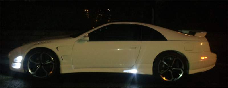
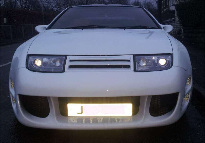
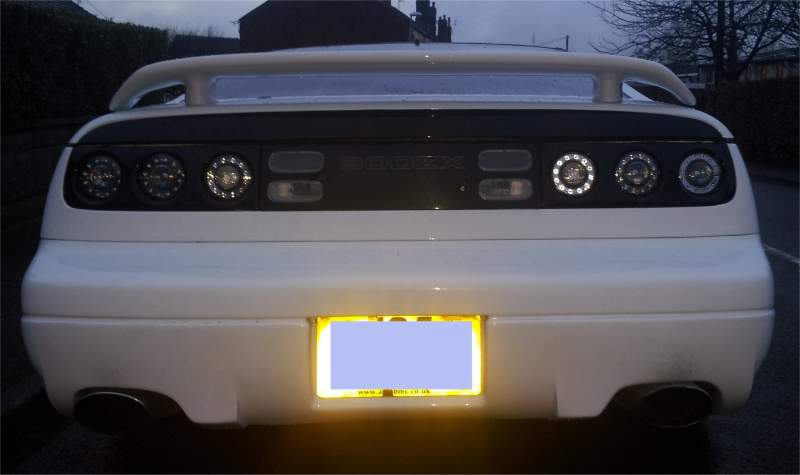
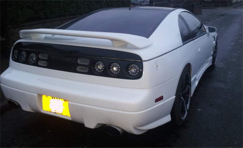
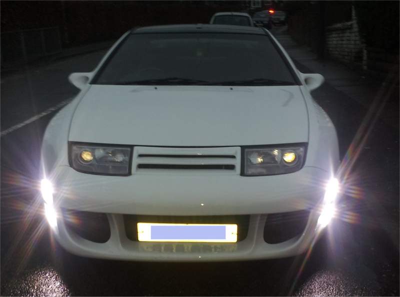
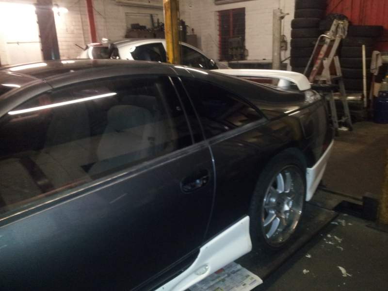
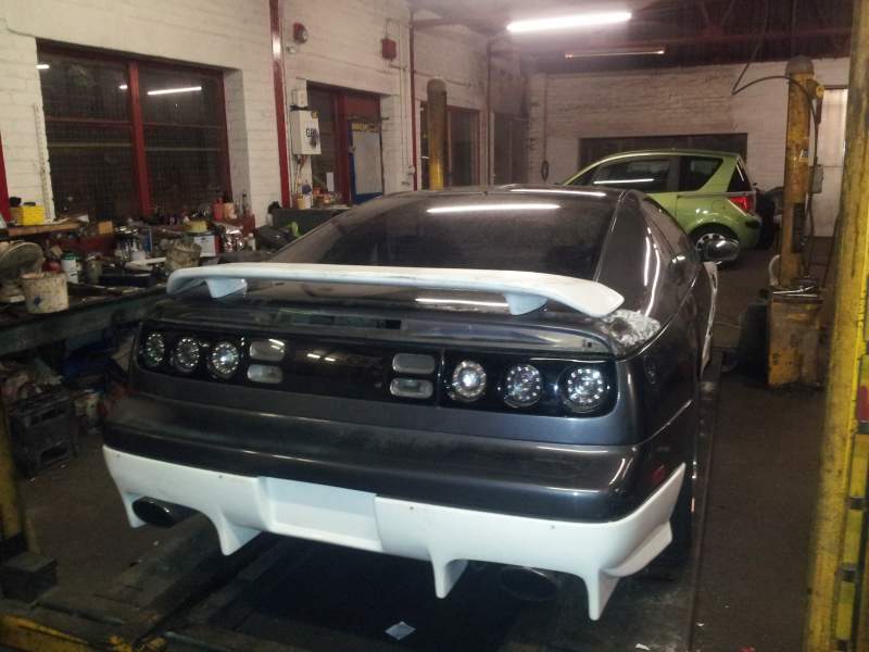
And A few more Rear spoiler is 99 spec 6 Pot Venom rear LED lights Colour is Audi 'R8' White with black roof panels, tinted targas, quarterlights and rear hatch - - - Updated - - - Oh and Ganador Mirrors

-
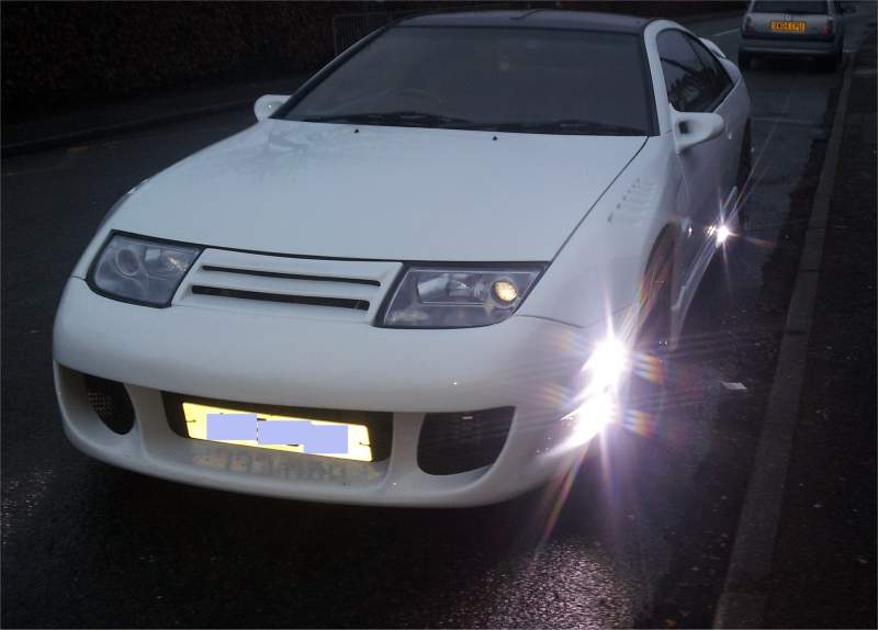
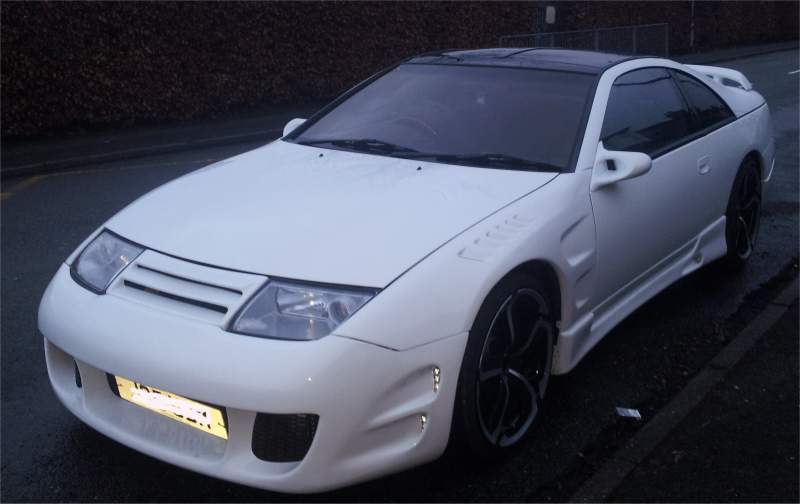
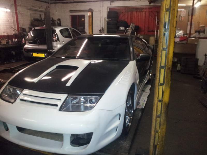
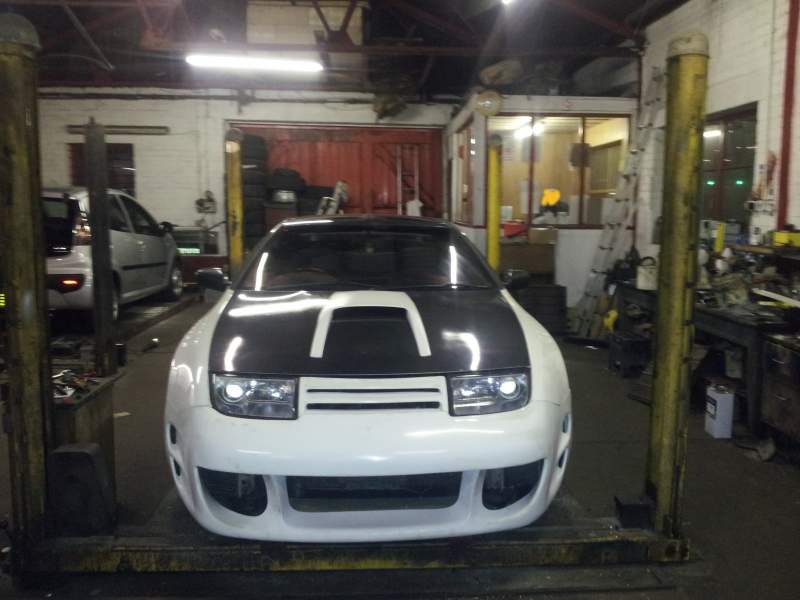
OK It's done and I like it :thumbup: Thanks to the various advice on here I made a few changes to the body kit In the end I left the bonnet bulge off - but have it sprayed white should I change my mind Personally I don't mind it being on, but like the car without it too The front bumper is the Viper V1. I had to get the centre part of the bumper modified so it sits level with the headlight panel The rear bumper is a Shark V1 but very much modified so it's hardly recognisable asa shark. However IMHO it looks great on the car and the tail pipes sit very nicely against the bumper now The side skirts are Demon - but with the vents modified to fit DRLs The wheels are Dotz Hanso 19" I have ordered some centre badges wit ha white Z on a black background but they are not here yet I've posted the pics here as no one can reply to my journal and I would of course like to hear any comments positive or otherwise The custom DRL / Indicators as most will know are my own design Some ideas are shamelessly stolen from pics of other members cars on here so I hope no one minds Anyway pics speak louder than words so here they are dicky
-
Mine comes back from the spray shop at the end of the week and funnily enough it will be 'Audi' White as used on the R8 etc with a few bits in black to set it off OK so it's not silver but I'll be uploading the pics anyways Anyone who has read my journal will know the car was originally graphite grey and see it has been stripped down and sprayed then put back together again rather than just sprayed over Rich
-
Regards sills, sill returns and floor pan Mine was in a pretty bad state (I uploaded pics of the corrosion problems to my journal and the forum) It cost me (in welding, materials and sill return repair panels) about £600 to sort it all out but having said that the results looked really good - again posted to my journal - and I'm happy with the work done for the price payed Hopefully that should see me OK now for a few years Rich
-
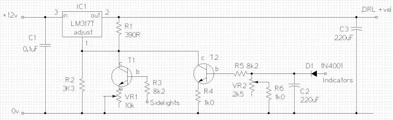
OK here is the circuit diagram for anyone interested in trying this at home :biggrin: Components required (inc Maplin stock codes) R1 - 390 ohm - Orange White Brown (or Orange White Black Black) M390R R2 - 3.3k ohm - Orange Orange Red (or Orange Orange Black Brown) Maplin: M3K3 R3, R5 - 8.2k ohm - Grey Red Red (or Grey Red Black Brown) Maplin: M8K2 R4 - 1k ohm - Brown Black Red (or Brown Black Black Brown) Maplin: M1K0 VR1 - 10k Variable Preset Resistor. Maplin UH16S VR2 - 2.5k Variable Preset Resistor. Maplin N51BR C1 - 0.1uF Capacitor (16V or greater) Maplin N43CJ C2, C3 - 220uF Capacitor (16V or greater) VH24V or DT64U D1 - Diode 1N4007 Maplin QL79L T1, T2 - BC547 Transistor Maplin: QQ14Q or BC549 Maplin QQ15R IC1 - LM317T Variable voltage regulator Maplin: UF27E A bit more about the components I built this using various bits I had lying around and most of the components are not that critical. However the values of the resistors are fairly important so use the ones I specified if possible. Resistors can be connected either way round Capacitor C1 could be pretty much any capacitor from about 0.1uF to 1uF (and rated 16V or higher) and could probably be left out all together. C3 could be any capacitor from about 10uF upwards (and rated 16V or higher) and again could probably be left out with no ill effects. C2 value is fairly critical to the circuit design so use a 220uF one rated 16V or higher C2 and C3 are 'electrolytic' capacitors - this means they will only work one way round. The curved plate on the circuit diagram is the negative one. D1 could be pretty much any rectifier diode, eg 1N4001, 1N4002 etc. Diodes only work one way round. The end with the 'stripe' is usually the end that the arrow points to on the diode symbol seen on the circuit diagram T1 and T2 could be pretty much any general purpose NPN transistor (for example BC107, BC108, BC549, 2N2222 or BC337 like I used). Transistors have three 'legs' called collector base and emitter (shown as e,b,c on the circuit diagram) and these must be connected correctly The LM317T voltage regulator also has three legs called 'in' 'out' and 'adjust' and must be connected the right way round. These regulators are made by a number of different manufacturers so the pin numbers may not match the ones in my diagram - so just take a little care you get it fitted the correct way. You need a 1.5Amp regulator - that is the one with a T at the end, not for example LM317L which will not handle sufficient current for this circuit. The Maplin one (code UF27E) has the same pin numbers as the one I used. The Variable Resistors VR1 and VR2 have three legs but we only need to connect to the middle leg and one of the end legs (either end it does not matter) Total cost of the components from Maplin, who are by no means the cheapest is £5.96 for each controller. That excludes the cost of the strip board I used to build the controllers on (about £4 and I have plenty left over), and the small boxes I put them into (Maplin: LH20W £3.69 each). Total should be around £20 for the two controllers - and you will probably be able to buy the parts needed much cheaper on ebay - I did!! My DRLs are fitted 6 each side of the car and draw about 0.5 Amps per side. The LM317T handles this without a heatsink - if your DRLs draw much more than 1 amp per side the LM317T will get pretty warm so will need keeping cool by bolting a metal heatsink to it! If you have DRLs that draw a lot more power than 1amp ask me and I will give you an upgraded version of the circuit. How it works ----------------- Refer to the circuit diagram below: The LM317T variable voltage regulator controls the voltage supplied to the DRLs. The higher the voltage the brighter they are. The voltage comes in on pin 3 (12volt supply) and comes out on pin 2 (variable voltage) The Voltage supplied to the DRLs via pin 2 depends on the values of the two resistors R1 and R2. connected to pin 1. The values of 390R/3k3 will supply 12Volts so the DRLs are on full brightness If you were to reduce the value of R2 then the voltage feeding the DRLs would decrease and they would dim. The transistors T1 and T2 act like electronic switches (or relays). When there is no voltage on the base connection they are switched off and have no effect on the LM317T voltage regulator. Now imagine you turn on the sidelights. This will put a 12V supply, via resistor R3, onto the base of Transistor T1. This causes T1 to turn on. R3 is there to limit the current supplied to T1 to a safe amount. When transistor T1 is turned on, it's just like turning on a relay connected between the 'c' and 'e' connections of the transistor. This connects VR1 across R3 and so reduces the resistance value. This causes the voltage supplied by the LM317T to reduce and the DRLs to dim. You can adjust the variable resistor VR1 to set the dimmed brightness level When you turn off your sidelights, transistor T1 turns back off and the DRLs go back to full brightness. Remember I said T1 is acting like an relay? That is perfectly true - and you could replace the transistor with a relay with the coil powered from your sidelights, and the contacts connecting VR1 across R2 and it would work just the same! But a transistor is a few pence, a relay is...... rather more and goes 'click' OK so that's how the dim function works. Now imagine you turn on your indicators. Ignoring the components C2, R6 and VR2 for the moment you see that everytime the indicator flashes on, you will supply 12V via the diode D1 and resistor R5 to the base of the transistor T2. This turns the transistor on and effectively connects the 1k resistor R4 across R2. This causes the combined resistance (R4/R2) to drop so much that the output voltage from the LM317 falls to about 3V. This is not enough voltage for the DRLs to light up, so they go out. Now when the indicators flash off, the transistor T2 would turn off again, which would cause the DRLs to come back on. We would have the DRLs/Indicators flashing alternately Yellow/White/Yellow/White... which is not quite what we want. This is where D1, C2, VR2 and R6 come in to play. Capacitors used in this way act like little rechargeable batteries. When your indicator flashes on, the 12V supply flows through diode D1 and almost instantly charges C2 to full capacity. Yes the 12V from the indicators is also powering the base of T2, thus turning the transistor on and the DRLs off. Now consider what happens when the indicators flash off. There is no more 12V supply coming from the indicator, so the capacitor C2 starts to discharge. It can't discharge back via the diode D1 and your indicator bulbs, as the diode only allows electric current to flow one way (the direction of the arrow on the symbol) So the capacitor C2 discharges mostly via VR2 and R6 instead (and also via R5 and the base connection of transistor T2 keeping the transistor turned on). VR2 sets the discharge rate. The lower you set the resistance of VR2 the faster C2 discharges. If we set VR2 such that it takes more about a second for C2 to discharge and T2 to turn off (and the DRLs to come back on) then before the capacitor C2 can fully discharge, the indicators flash back on instantly charging it back up again. C2 can never fully discharge because everytime it gets down to about half charge the indicators flash back on and charge it up again. This keeps transistor T2 turned on and the DRLs turned off. Only when the indicators stop flashing can C2 finally discharge, T2 turns off and the DRLs come back on. Adjust VR2 so that the DRLs stay off while the indicators are flashing, and take about a second to come back on afterwards R6 is there to stop you setting the resistance of VR2 too low. If R6 was not there and you turned VR2 all the way over to one end then the value of VR2 would be around zero ohms so you would create a short circuit between the indicator supply and chassis, via D1. Something would have to give, most likely D1 would explode in a slightly spectacular manner or VR2 would simply fry and burn! Because R6 is there this can't happen - the total resistance of VR2+R6 can only be adjusted between 1k and 3.5k C1 and C3 don't do anything particularly interesting, they are there to filter out voltage spikes and surges which could otherwise cause the LM317T to become unstable and the brightness of the DRLs to fluctuate. In most cases they are pretty much redudant and everything would still function normally even if you removed them So that's how it works, I hope my explanation is clear enough for anyone with only a basic knowledge of electronics to be able to understand my design. Rich
-
Thanks for the advice guys - I went down to the body shop today and had a good chat about what I want. With some modification this rear end will look OK me thinks...... watch this space :biggrin:
-
Big ask I know.... but is anyone here good with photoshop and can re-do that back end without the fin things on the bumper? Or maybe just stumps of them
-
Right thanks - that kinda goes with what I was feeling It's the two fins and placement of them on the rear bumper in particular that has been niggling me - though most other folks say they like it cheers Rich
-
I can't believe it but went to pick up my new Alloys today and while chatting with the guy (as I got to know him a bit) I showed some pics of the new body kit and guess what he also likes that rear bumper! So.... is it just me not totally enamoured with it - guys at the garage, guys at the body shop, two mates and guy from the alloys shop all like it. Just one PM from a member on here who agrees with me it needs toning down somewhat So just to settle this - is it just me who needs to come to love it? It seemed like a good idea when I bought it but.......... Rich
-
Nice to hear that Mark Was I on the right track with how to do it?
-
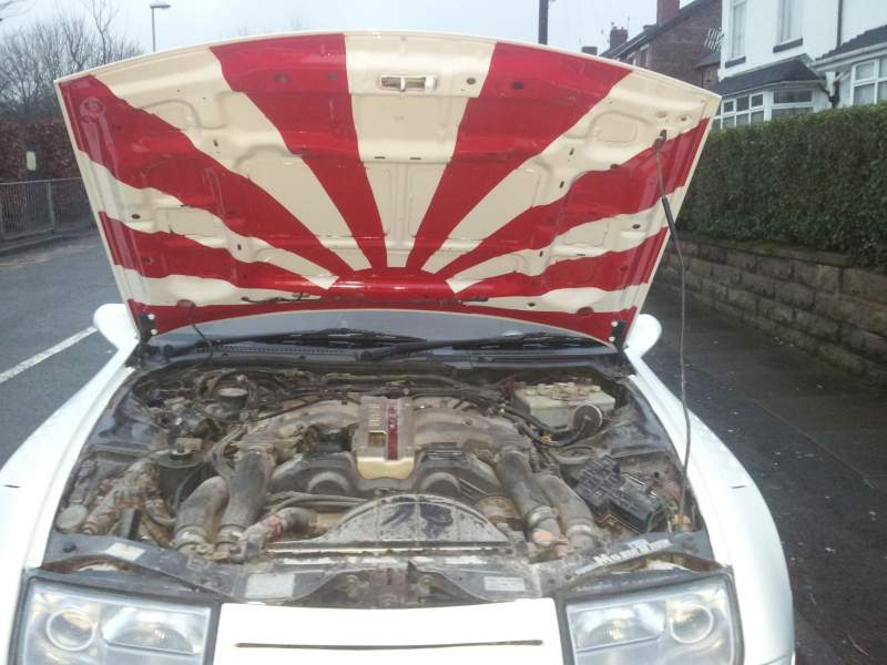
I'm gonna get the car sprayed that really sharp white which Audi put on their R8 - apart from the small panel over the top of the windscreen and the one behind the targas which are gonna be black. Intendeng to get the targas tinted dark, the back hatch and quarter lights already are tinted. Personally I quite like the scoop that way round as it has an agressive look, I think, but I did ask for opinions so fair game Anyway it will be blended in, not just sitting there. Also other way round rain water would run down the bonnet and into the scoop when parked
-
I also have the genuine nissan illuminated rear panel Really Really want those illuminated rear quarter shades, has anyone thought of making replica ones? Looks like you would need to get some standard ones etched or screen printed or something - maybe an adhesive printed film attached to the inner surface would be easier..... then fit a narrow EL panel or EL tape behind that. Then over the top some of that window tinting plastic film stuff to seal it all in and tint the window?? Sounds like a fun project.. I may have a go unless someone else already does these
-
LOL I didn't read the thread till this morning! Nahh I could have taken it anyway though constructive criticism/suggestions is what I would like. Then I'll make my own mind up anyways lol So custmisation is a very personal thing - but hope I have little better taste than that pink one! Im quite happy with the way this is coming along but don't like the rear bumper now i have it on the car. Guys at the garage, the guys who've taken it for prep work/spraying and a couple friends who have seen it all think it suits the car - but me.... I'm really not sure I'm taken with it For non subscribed members (who I don't think can view my journal?).... I've reposted pics herre and I'm thinking of shortening those two fins that come down either side of the tail pipes, maybe trying to get a curved shape to the bottom of them. Also I think it would look better with the fins evenly spaced around the exhaust if it can be modded that way. Also thinking of fabricating a ribbed 'diffuser' to fit between them across the centre rear if it can be done :blink: Car is now in prep work and blending in, so best time to change things.
-
I posted a lot of pics on my journal and also some requests for comments/advice Especially about that rear bumper I fitted cos I really ain't totally inspired by it now it's on the car Anyway I didnt realise until PMed, that other members can not reply on my journal thread apart from mods and admins! So anyways here are the pics http://www.300zx.co.uk/forums/showthread.php?165840-Dicky-s-Zed-Project Yeah I know its good to do your own thing but I'm very much open to opinions and suggestions as I go along.... cheers Rich