Jump to content
View in the app

A better way to browse. Learn more.

300ZX Owners Club

A full-screen app on your home screen with push notifications, badges and more.

To install this app on iOS and iPadOS
  1. Tap the Share icon in Safari
  2. Scroll the menu and tap Add to Home Screen.
  3. Tap Add in the top-right corner.
To install this app on Android
  1. Tap the 3-dot menu (⋮) in the top-right corner of the browser.
  2. Tap Add to Home screen or Install app.
  3. Confirm by tapping Install.
Posted

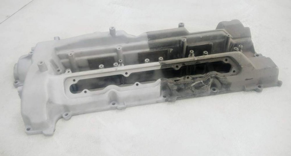
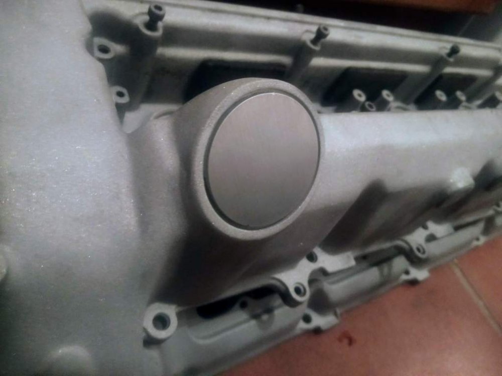
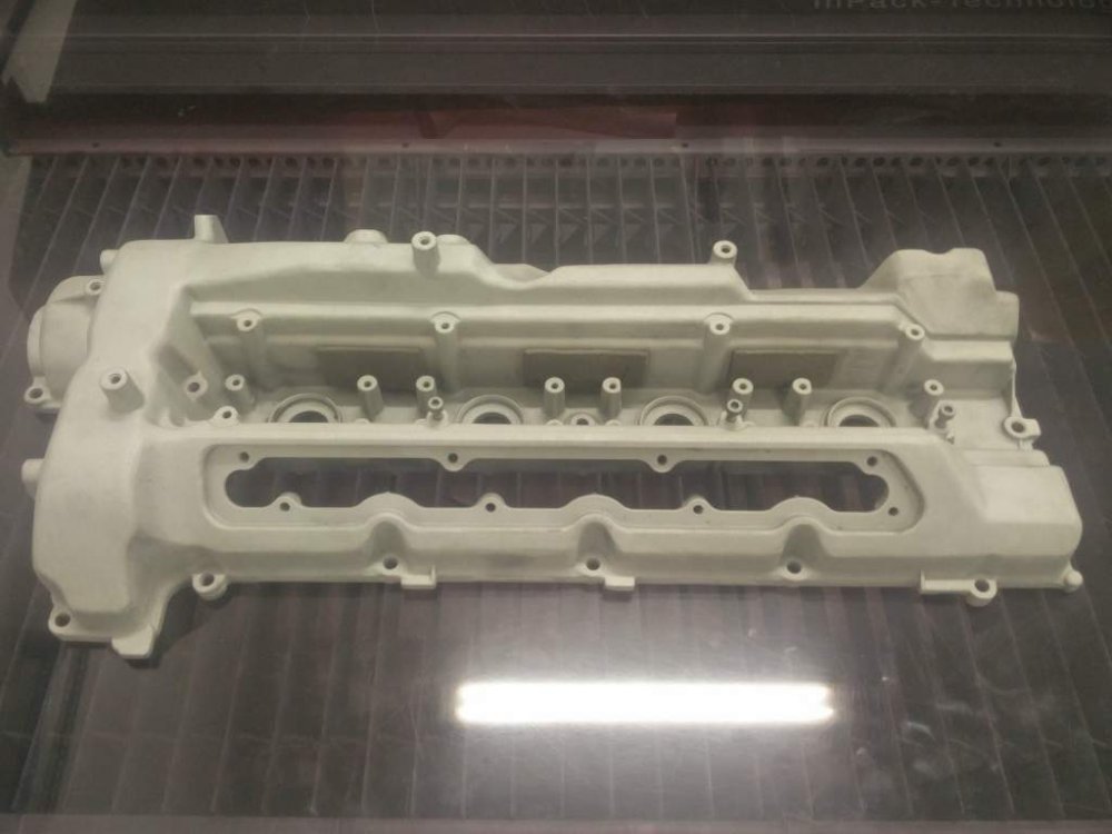
Today I collected this "little" beauty for my Slicktop Project.


Nissan/Infiniti VH45DE

4.5 Litre 90degree V8


IMG_20160717_184429.jpg


Many of you will be familiar with the VH45DE, our very own John Dixon has the 500ZX and our U.S forum member PerformanceVH has an excellent build thread on his VH45 transplant. This engine in in fact the twin to J.D's 500zx engine, imported and originally built alongside it, albeit to a less aggressive spec, as owned by forum member Friday(Leigh).


I am a big advocate of the Z32's VG30, its a great engine and had this new opportuniity not come up I would be fitting a set of larger turbos, injectors, intercoolers..etc to the VG30 right now. But I've been there before, its nothing new and I would only be doing the same as so many others have done over the years - and besides my own personal fascination with having a responsive high revving "race" V8 I see this as a bit of an engineering exercise in itself due to the amount of custom engineering and fabrication required.


The VH45DE is an engine that has interested me for the past 10 years. Its the engine Nissan had originally considered using in the Z32, and the same base architechture for the V8 engine that has been used in racing with the 300zx, 350z/370z and GTR since the 90's and by a large proportion of the WEC/Le Mans LMP2 grid until recently.


I was so close to going this route many years ago when I started with the Slicktop project, but I just wasn't in the right position then to be able to take on such a challenge...I hope I am now.


I intend to stay normally aspirated. The engine aleady has some mild headwork done, but Im looking at going a bit more aggressive than the current setup and utilising Intake and Exhaust tuning with the aim to hit that magic 100hp/litre. Although hitting it is not critical, Im not chasing high peak numbers, but rather an engine that delivers the power, noise and response I can enjoy in my lightweight slicktop.


  • Head porting and Valvetrain work (tbd)
  • Individual Throttle bodies (ITB's) with tuned length velocity stacks and a Dual Inlet Intake chamber.
  • Inconel Equal Length 4-1 Primaries into a dual exhaust system with X-pipe
  • Standalone ECU Management with custom wiring.
  • Dry Sump Oil System
  • Electric Waterpump and PAS Pump
  • ...and more

IMG_20160717_184805.jpg

IMG_20160717_184812.jpg

Edited by Yowser

  • Replies 53
  • Views 6.2k
  • Created
  • Last Reply

Top Posters In This Topic

Posted Images

Featured Replies

Picked up this little number a few weeks back to be fitted when it goes off to the bodyshop.


[ATTACH=CONFIG]102197[/ATTACH]

[ATTACH=CONFIG]102196[/ATTACH]


Did you make the bumper Dave?

Electric Water pump and Power Steering pump, so the only ancillery runing from the crank is the 3-Stage Dry Sump pump.


THe VH is chain driven.


Is that to free up a few extra bhp or for convenience fitting the engine?

  • Author
Is that to free up a few extra bhp or for convenience fitting the engine?


Both reasons, Freeing up parasitic drag on the engine for additional power and Packaging Limitations.


But an Electric Water pump reduces the risk of cavitation at higher rpm than the original was designed for, it can also be setup to reduce heat soak with the engine off, warm the engine up quicker and efficiently manage the Coolant temperature at all rpm's and loads, rather than the stock mechanical setup which is always a compromise.


The Electric PAS pump is mainly due to packaging limitations, and the power it can free up when setup correctly. Its essentially an EHPAS setup (electric-hydraulic), so wont have an effect on the way the original Hydraulic PAS works or feels.


- - - Updated - - -


Did you make the bumper Dave?


Purchased from a UK Trader, however Im not sure if they are doing any more.

So is the water pump from another vehicle or completely aftermarket?


How about the alternator, can the extra demand be supplied by the stock unit or do you need something with higher amperage?


And the cooling fan, is it viscous as stock? I'm guessing you'll have something electric as well to work with the water pump overrun?


Sounds really well thought out.

  • Author
So is the water pump from another vehicle or completely aftermarket?


How about the alternator, can the extra demand be supplied by the stock unit or do you need something with higher amperage?


And the cooling fan, is it viscous as stock? I'm guessing you'll have something electric as well to work with the water pump overrun?


Sounds really well thought out.


Aftermarket Water pump (Davies Craig 130 http://daviescraig.com.au/product/ewp130-alloy-kit-12v-part-no-8080) , which bolts directly onto a custom aluminium Radiator mounted at an angle to fit under the Nose of the Z with electric fan setup, rather than in the stock bay location. Also an Aftermarket in-line Thermostat, as the stock Waterpump and Thermostat housing have been removed, blanked off and new inlet/outlets Fabricated to provide additional clearances.


Stock Alternator output should be fine but its an old design and quite heavy. There are more modern smaller lightweight aluminium alternators that may end up replacing it. I need to design and fabricate a custom Aluminium bracket for it too.

  • 3 weeks later...
  • Author

Having the first Head CMM Inspected/Measured during Intake porting progress at work :


IMG_20161109_184155.jpg

IMG_20161109_183906.jpg


Some Initial ITB/Velocity Stack/Airbox draft designs. Top Mount Fuel Rail setup with Bosch Injectors


Working to a ~350mm Valve head to bellmouth opening length.

Shorter TB to Valve ratio length with Injector just after the Throttle to take advantage of local turbulance for fuel atomization. ~10litre Airbox Volume, to (hopefully) avoid intefering with ITB Flow.


Trying to make the most out of the limited clearances available.


inlet5.JPG

inlet2.JPG

Edited by Yowser

I think you need to be more creative with your stack shapes!!!


I'll just leave this here as an example

m5_intake_stacks_copy1.jpg


:scared: :wacko: :lol: :laugh: :blink:

  • Author
I think you need to be more creative with your stack shapes!!!


I'll just leave this here as an example

[ATTACH=CONFIG]102796[/ATTACH]


:scared: :wacko: :lol: :laugh: :blink:


E39 M5 V8. Madness.

I don't know a huge amount about velocity stacks but know you can change features of them to give different power characteristics, right? Do you have a particular aim with yours?

  • Author
I don't know a huge amount about velocity stacks but know you can change features of them to give different power characteristics, right? Do you have a particular aim with yours?


Thats right, the main one being the entire intake runner length from the Intake valve (in the head) to the Velocity stack opening. Its to do with the pressure waves (Helmholtz resonance) from the opening and closing of the Intake valve, and taking advantage of the pressure change and the subsequent pressure wave to improve Volumetric efficiency. I am aiming for the most gains between 6000-9000rpm, without comprising low-end characteristics too much.


You are essentially setting the length for the optimum rev range you are aiming to make the most power for. Longer=lower rpm, Shorter=higher rpm. Most aftermarket ITB setups are a comprimise between the space available and the ideal runner length. You will often see setups with far too short runner lengths for the engine characteristics.


You can also alter the ratio between Throttle valve and intake valve length, versus throttle valve to Bellmouth length - compromising between optimum fuel mixture and throttle response.


There are minor characteristic changes like tapering of the bore and the profile of the bellmouth which all aid in improving the velocity of the flow, and everything needs to be matched in diameter as a ratio of the mating system. You essentially have to take into account the cross section area throughout the system - Valve head diameter (minus valve stem diameter), Cylinder heat port diameter, runner diameter, throttle body diameter and Velocity stack diameter - Ideally tapering at an optimum ratio at all times with the aim of increasing flow velocity without restricting flow rate.

Edited by Yowser

Having the first Head CMM Inspected/Measured during Intake porting progress at work :


[ATTACH=CONFIG]102790[/ATTACH]

[ATTACH=CONFIG]102791[/ATTACH]


Some Initial ITB/Velocity Stack/Airbox draft designs. Top Mount Fuel Rail setup with Bosch Injectors


Working to a ~350mm Valve head to bellmouth opening length.

Shorter TB to Valve ratio length with Injector just after the Throttle to take advantage of local turbulance for fuel atomization. ~10litre Airbox Volume, to (hopefully) avoid intefering with ITB Flow.


Trying to make the most out of the limited clearances available.


[ATTACH=CONFIG]102789[/ATTACH]

[ATTACH=CONFIG]102788[/ATTACH]


The what now?? It's all gone straight over my head but it looks cool as f@*k, this is all custom designed by yourself mate? Really wish I went into mechanics and engineering:thumbup1:

Changes like tapering of the bore and the profile of the bellmouth


If I dare ask a question...

Are you not doing anything with tapering yours or doing better bellmouths because of space? manufacturing? both? other reasons?

  • Author
If I dare ask a question...

Are you not doing anything with tapering yours or doing better bellmouths because of space? manufacturing? both? other reasons?


Space constraints - Im clashing on the bellmouth if I taper or go larger on the Belllmouth diameter itself.


It is just a draft at this stage though, I cant move to manufacturing till I take some final measurements, and I cant do that as the heads are off the Block currently.

  • Author
The what now?? It's all gone straight over my head but it looks cool as f@*k, this is all custom designed by yourself mate? Really wish I went into mechanics and engineering:thumbup1:


Thanks, yeah all custom.

So what do you do in terms of choosing camshafts? Do you choose something that works to complement the high powerband?

  • Author
So what do you do in terms of choosing camshafts? Do you choose something that works to complement the high powerband?


Yep, exactly, everything contributing to the same goal. In this instance I bought the engine with uprated cams already. They are a little milder than I would of hoped, but they should be up to the job.


If not, I will have to consider getting them re-profiled later on. I am replacing the Valvesprings to cope with the higher rpm loads though. Im also going to go against the grain a little and attempt to stick with Hydraulic lifter setup, which typically you would replace for a Solid setup at these RPM goals, but we'll see how it copes.

Edited by Yowser

Is that cost saving re the lifters?


Have you decided on a management system yet and are you going MAF or MAP/TEMP?

  • Author
Is that cost saving re the lifters?


Have you decided on a management system yet and are you going MAF or MAP/TEMP?


Not really, you can convert the HLA's into Solid by dissaembling and shimming the internals which costs next to nothing, but there are a number of benefits to the HLA setup itself, such as quieter, low maintenance. "Apparantly" the stock HLA setup on the VH engine is retained in the SuperStock racing series over in New Zealan where they are taking them to 9000rpm+


Im going MAP setup with a Emerald K6, founded by one of UK's most renowned tuners - Dave Walker, and recommended highly by John Dixon.

Edited by Yowser

  • 3 months later...
  • Author

Winter for me has mainly consisted of working obscene hours for the build up of the F1 Season, but now that the Pre-season testing is out of the way Im finding myself with some spare time for the V8 Z. :clap:


Finished the Head Intake porting, and will be sent off to have the gasket surfaces skimmed, so I can start the assembly with the New Uprated Valve Springs (Thanks to VHPerformance).


Finished the Lower Intake design and is with my Machine shop for CNC Machining, to be done in-between paid jobs.


inlet_capture.JPG


Various Lasercut Blanks, bungs, brackets have been produced and test fitted to engine.


IMG_20170315_233722.jpg


Aluminium Dry sump pan fitted to engine


IMG_20170312_191321.jpg


I've started work on the Custom fuel setup, using Dual Aluminium extrusions and machined for 14mm Bosch top feed injectors, in a parallel configuration, Adjustable FPR with Black AN8 Fittings and Black Braided lines.

IMG_20170305_162607_459.jpg

IMG_20170308_234448.jpg

Edited by Yowser

  • Author

Shotblasted the Cam covers the other week, in preparation for some modifications and then Powder coating.


IMG_20170308_234005.jpg


Planning on a Wrinkle Blank Finish.

IMG_20170306_192432.jpg

IMG_20170306_190922_983.jpg

  • 2 weeks later...
  • 4 months later...

Join the conversation

You can post now and register later. If you have an account, sign in now to post with your account.

Guest
Unfortunately, your content contains terms that we do not allow. Please edit your content to remove the highlighted words below.
Reply to this topic...

Recently Browsing 0

  • No registered users viewing this page.

Important Information

Terms of Use

Configure browser push notifications

Chrome (Android)
  1. Tap the lock icon next to the address bar.
  2. Tap Permissions → Notifications.
  3. Adjust your preference.
Chrome (Desktop)
  1. Click the padlock icon in the address bar.
  2. Select Site settings.
  3. Find Notifications and adjust your preference.